English version

HiperLAN/2 : a Quality of Service enabling Wireless LAN


Introduction ]

H/2 Standard ]

TCL H/2 Prototype ]

 Animated Tour

[ Prototype performances ]

TCL Activities ]


An animated tour of ITE-TCL H/2 demonstration platform

Click on pictures to launch video clips. Video is  encoded in DIVx-MPEG4 format.

DivX codec is needed :  

Prototype description

click to launch


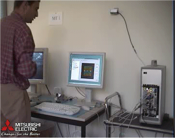
HiperLAN/2 protototype is embedded in a compact PCI rack and is connected to a PC (under Linux OS) hosting H/2 non-real time software and applications

  • Applications in the Access Point include:

    • a video streaming server

    • a TCP traffic generator for background traffic load

    • 2 live video capture clients

    • a Web browser

  • Applications in terminal #1:

    • a video streaming client, with a QoS enabled connection 

    • a camera for live video capture

    • a Web server

    • a TCP client for traffic generator

  • Applications in terminal #2:

    • a video streaming client, with a best-effort connection 

    • a camera for live video capture


Monitoring tools

click to launch

At Physical layer, a monitoring tool provides graphical views of instant values of the main parameters that characterise the PHY layer. Among these views, the constellation picture is a good way to display the current modulation scheme with a first idea of the link quality.
The video shows the effect of a dramatic change in propagation conditions, current physical modulation moving between 64-QAM and BPSK.

Another tool monitors Data Link Control layer. It dynamically displays, among other statistics, instant throughput of each opened DLC.

In the video screen capture, we have:

  • Blue curve: TCP background traffic (above 10 Mbit/s)

  • Yellow and green curves: video streaming (about 12 Mbit/s each)

  • Light blue and red curves: Live videos (around 3 Mbit/s each)

  • Pink curve: Web browsing traffic (page refresh every 10 s)

Flow classification capabilities, connections handling and resource scheduling make the system able to share available bandwidth among applications according to their needs.

In this example, when the Web client requests bandwidth for page refresh (pink curve), resources are taken from the elastic stream pool without impacting Constant Bit Rate (CBR) traffic while total system bandwidth remains constant. Only background TCP traffic (blue curve) experiments a drop in allocated bandwidth.

If a video stream is stopped, resources go back to the pool and can be affected to background TCP traffic.

Bandwidth sharing and QoS support

click to launch

Wireless transmissions are very likely to experiment radio perturbations leading to a drop in the overall capacity.

Let us show how the system reacts:

  • Dynamic Link Adaptation algorithm switches to a more robust physical mode, leading to a reduction in available bandwidth

  • This decrease in resource affects the elastic traffic but not the one under CBR scheduling control.

In a first step, only the TCP traffic (blue curve) is affected. If radio perturbation becomes harder, the video stream defined as best-effort (yellow curve) is affected next, but CBR streams still get the bandwidth they have requested.

Best-effort video plays on the main screen and CBR one in overlay. Effect of radio perturbation on applications is clear: the first one encounters freezes while the second one is completely unaffected.

Radio perturbation and QoS support

click to launch

* List of Acronyms